1. Why Water in Ductwork is a Critical Building Failure
Water intrusion into HVAC ductwork is one of the most consequential building failures an inspector can encounter. Unlike a leaking pipe or a wet wall cavity — where the damage is localised — water in a duct system is distributed throughout the building by the very mechanism designed to maintain air quality. Every cubic metre of air that passes through a wet duct section picks up moisture, particulates, and potentially microbial contamination, and delivers it to every occupied space the system serves.
The sources of water in ductwork are varied: condensation from inadequate insulation or vapour barriers, roof or wall leaks that breach duct penetrations, plumbing leaks above or adjacent to duct runs, flooding events, and — in flex duct systems — pooling from improper installation that creates low spots where condensate accumulates. In each case, the presence of water creates the moisture conditions that support biofilm formation, mold growth, and progressive structural deterioration of the duct system.
The challenge for inspectors is that water damage in ductwork is often invisible from the outside. Sheet metal ducts may show no external sign of internal moisture. Flex duct may appear intact while harbouring standing water in a sag. Fibreglass liner may be saturated without any visible surface indication. This is precisely the problem that in-duct thermal imaging is designed to solve.
Mold growth can begin on wet duct surfaces within 24–48 hours under favourable temperature and nutrient conditions. Water intrusion that is not detected and remediated promptly escalates from a moisture problem to a contamination problem — with significantly higher remediation costs and health implications.
2. The Limitations of External Thermal Cameras for Duct Inspection
External infrared cameras — handheld or mounted — are the standard tool for building moisture investigation. They are highly effective for detecting moisture in walls, ceilings, and floors by identifying the temperature differential between wet and dry building materials. However, they have a fundamental limitation when applied to ductwork: they can only image the external surface of the duct.
For a duct run that is accessible and uninsulated, an external thermal camera can sometimes detect temperature anomalies that suggest internal moisture. But in practice, most duct runs are insulated, concealed within ceiling plenums or wall cavities, or located in areas with insufficient temperature differential to produce a detectable external thermal signature. The external camera sees the insulation jacket, not the duct interior — and a wet duct interior may be thermally masked by its insulation.
In-duct thermal imaging eliminates this limitation entirely. By placing the thermal sensor inside the duct, the VD-FID's thermal mode images the duct interior surface directly — the sheet metal, the liner, the joints and seams — at the precise location where water intrusion occurs. There is no insulation to penetrate, no external surface to interpret, and no ambiguity about whether an anomaly is inside or outside the duct.
- Effective for wall/ceiling moisture
- No duct access required
- Wide area coverage
- Cannot image duct interior directly
- Blocked by insulation
- Misses concealed duct runs
- Requires temperature differential
- Direct duct interior imaging
- Insulation does not interfere
- Reaches concealed duct runs
- Precise leak location to cm
- Maps temperature distribution
- Detects condensation zones
- Combines with UV and white-light
3. How Infrared Thermography Detects Water and Moisture
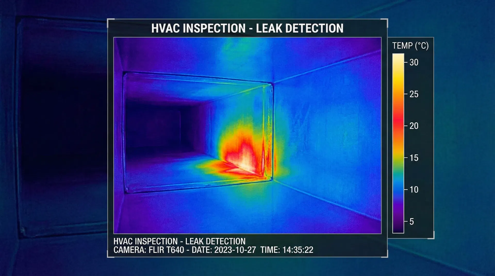
Infrared thermography detects temperature differences at surfaces by measuring the infrared radiation emitted by those surfaces. The fundamental physical principle is that all objects above absolute zero emit infrared radiation, and the intensity and spectrum of that radiation is a function of the object's temperature and emissivity. A thermal camera converts this radiation into a false-colour image — typically with warm areas shown in red/yellow and cool areas in blue/purple — that makes temperature differentials immediately visible.
Water and moisture are detectable by thermal imaging for two reasons. First, water has a high specific heat capacity — it absorbs and releases heat more slowly than most building materials. This means that a wet area will be cooler than its surroundings when the environment is warming (evaporative cooling effect), and warmer than its surroundings when the environment is cooling. This thermal lag creates the temperature differential that the camera detects.
Second, evaporation is an endothermic process — it absorbs heat from the surface. A wet duct surface that is actively evaporating will be measurably cooler than the surrounding dry surface, even under steady-state thermal conditions. This evaporative cooling signature is the primary detection mechanism for active water leaks and saturated liner material in duct inspection.
4. In-Duct Thermal Mapping: What the VD-FID Measures
The VD-FID's thermal mode produces a continuous false-colour thermal map of the duct interior as the probe advances. The system measures surface temperature across the field of view, with temperature resolution sufficient to detect differentials of less than 0.5°C — well within the range needed to identify evaporative cooling from active leaks or condensation zones.
In practice, the thermal map reveals several categories of anomaly. Active water leaks appear as sharply defined cold spots at the leak point, often with a characteristic drip or streak pattern extending downward from the source. Saturated liner material appears as a diffuse cold zone covering a larger area, with less defined edges. Condensation zones appear as cold areas correlated with duct geometry — typically at transitions, bends, and areas of reduced insulation. Thermal bridges — points where insulation is absent or compressed — appear as localised temperature anomalies that may or may not be associated with moisture.
| Anomaly Type | Thermal Signature | Typical Cause | Urgency |
|---|---|---|---|
| Active leak | Sharp cold spot, defined edges | Roof/plumbing leak, joint failure | Critical |
| Saturated liner | Diffuse cold zone, large area | Past leak, flooding, condensation | High |
| Condensation zone | Cold area at transitions/bends | Inadequate insulation, dew point | Medium |
| Thermal bridge | Localised temp anomaly | Insulation gap, fastener penetration | Low–Medium |
| Standing water | Cold pool at low point | Flex duct sag, improper slope | High |
5. Identifying Active Leaks vs. Residual Moisture
One of the most practically important distinctions in duct moisture investigation is between an active leak — where water is currently entering the duct — and residual moisture — where water entered in the past and has partially dried, leaving saturated material or staining. This distinction affects remediation scope, urgency, and the attribution of responsibility in insurance and litigation contexts.
Active leaks typically produce a stronger, more defined thermal signature because the evaporative cooling effect is ongoing. The cold spot will be at or near the leak point, and the temperature differential will be most pronounced when the HVAC system is running (increasing airflow and evaporation rate). Residual moisture produces a weaker, more diffuse signature that may vary with ambient temperature and humidity conditions.
The VD-FID's SpectraSwitch™ capability is particularly valuable for this distinction. Switching from thermal mode to UV 365 nm mode in the same area allows the inspector to correlate thermal anomalies with fluorescence — active biofilm growth (indicating ongoing moisture) versus staining without fluorescence (indicating past moisture that has dried). This multi-spectrum correlation provides a more complete picture of the moisture history than either technique alone.
6. Condensation Zones and Thermal Bridge Detection
Condensation within ductwork is a chronic moisture source that is distinct from acute water intrusion events. It occurs when the duct surface temperature falls below the dew point of the air inside the duct — a condition that arises from inadequate insulation, thermal bridges (points where insulation is penetrated or compressed), or operating conditions that produce unusually cold supply air.
Thermal bridges are particularly insidious because they are structural features of the duct system that cannot be remediated by cleaning alone. A metal hanger, a fastener penetration, or a compressed insulation seam creates a localised cold spot on the duct surface that will produce condensation whenever the dew point conditions are met — regardless of how thoroughly the duct has been cleaned. Identifying and documenting thermal bridges is therefore an important part of a complete forensic duct investigation, as it informs the remediation scope and identifies the root cause of recurring moisture problems.
In-duct thermal mapping with the VD-FID identifies condensation zones and thermal bridges precisely and reproducibly. The probe advances through the duct, and the thermal map records the temperature distribution along the entire run. Areas of persistent cold — correlated with duct geometry, insulation transitions, and hanger locations — are flagged for further investigation and documented with timestamped thermal images.
7. Thermal Mapping for Insurance and Litigation
Thermal imaging evidence is well-established in building damage litigation and insurance claims. Courts and insurance carriers routinely accept thermographic inspection reports as evidence of moisture intrusion, provided the inspection was conducted by a qualified thermographer using calibrated equipment and a documented methodology. The RESNET (Residential Energy Services Network) and InterNACHI standards for thermographic inspection provide the professional framework within which such inspections are conducted.
In-duct thermal mapping adds a dimension to this evidence base that external thermography cannot provide: direct documentation of moisture conditions at the duct interior surface. This is particularly valuable in disputes where the question is not whether there is moisture in the building, but whether the HVAC system was the source or pathway of contamination. An in-duct thermal map that shows active water intrusion at a specific duct joint — correlated with a roof leak directly above that joint — provides compelling evidence of causation that external thermography alone cannot establish.
For insurance claims, the thermal map also serves as a scope documentation tool. By precisely identifying which duct sections are affected by moisture, the inspector can define the remediation scope with specificity — avoiding both under-remediation (leaving affected sections in place) and over-remediation (replacing sections that are not actually affected). This precision benefits both the insured and the carrier by ensuring that the claim is accurate and the remediation is effective.
8. Integration with UV and White-Light Inspection
The full value of the VD-FID's SpectraSwitch™ system is realised when thermal, UV, and white-light inspection are conducted as an integrated workflow rather than as separate inspections. Each mode provides information that the others cannot, and the combination produces a complete evidence picture that is greater than the sum of its parts.
A recommended integrated inspection sequence begins with a white-light pass to document structural conditions and identify areas of visible concern. The thermal pass then identifies moisture anomalies — active leaks, saturated liner, condensation zones — that may not be visible under white light. Finally, the UV pass reveals biofilm and mold colonisation, which is often concentrated in the areas identified as moisture-affected by the thermal pass. The correlation between thermal anomalies and UV fluorescence is itself diagnostic: areas with both thermal and UV anomalies represent active contamination sources, while areas with UV fluorescence but no thermal anomaly may represent past moisture events that have dried.
9. NDT Standards for Thermographic Inspection
Thermographic inspection is a well-established NDT (Non-Destructive Testing) methodology with a mature standards framework. The primary international standard is ISO 18434-1 (Condition monitoring and diagnostics of machines — Thermography), which provides general principles for thermographic inspection methodology, equipment requirements, and reporting. For building applications, ASTM E1933 (Standard Practice for Measuring and Compensating for Emissivity Using Infrared Imaging Radiometers) and ASTM E1934 (Standard Guide for Examining Electrical and Mechanical Equipment with Infrared Thermography) provide additional guidance.
For in-duct thermal inspection specifically, the relevant NDT principles include: equipment calibration and documentation, inspector qualification (Level I or Level II thermographer certification is standard), environmental condition recording (ambient temperature, humidity, HVAC operating state), and image documentation with temperature scale, emissivity setting, and timestamp. The VD-FID system is designed to facilitate compliance with these requirements through its integrated recording and documentation capabilities.
Inspector qualification is an important consideration for forensic applications. Thermographic inspection reports that will be used in litigation or insurance proceedings should be prepared by a certified thermographer — typically Level II or Level III under the ASNT (American Society for Nondestructive Testing) certification scheme. The VD-FID provides the tool; the inspector provides the expertise and the professional credibility that makes the evidence admissible and persuasive.
10. Field Protocol for Thermal Duct Inspection
The following protocol is recommended for in-duct thermal inspection using the VD-FID. It is designed to produce defensible, reproducible results suitable for insurance, litigation, and remediation planning purposes.
Thermal IR Mapping Built In
- In-duct thermal / IR imaging mode
- Temperature resolution < 0.5°C
- False-colour thermal mapping
- SpectraSwitch™ — thermal + UV + white LED
- Probe diameters 0.85–8 mm, reach to 30 m
